Results 1 to 10 of 10

Thread: 77 connector delete question.. check this out.

  1. #1
    Senior Member Gloomshadow's Avatar
    Join Date
    Apr 2011
    Location
    Orlando Florida
    Posts
    2,493

    77 connector delete question.. check this out.


  2. #2
    Senior Member Gloomshadow's Avatar
    Join Date
    Apr 2011
    Location
    Orlando Florida
    Posts
    2,493
    he checked resistance on both black wires both were "0"... hes thinking that they can hook up either way but isn't 100% sure.

  3. #3
    Senior Member lancruza's Avatar
    Join Date
    Dec 2009
    Location
    King, NC
    Posts
    526
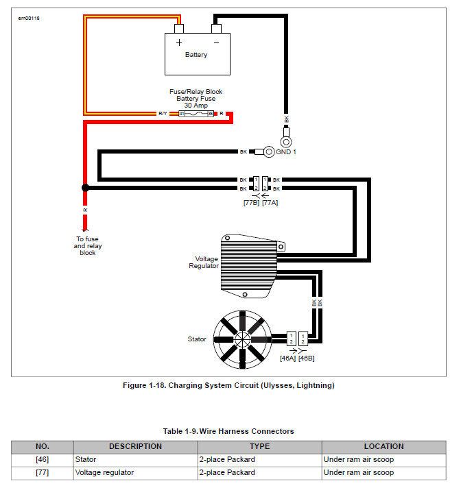
    The two black wires coming from the regulator should have dc voltage on them when the bike is running. Output should be 14-14.4v with the bike running. You could start the bike and measure across the two black wires with a voltmeter. If you are showing positive 14 voltage then the wire with the red lead from the voltmeter would be your positive.

  4. #4
    Senior Member lancruza's Avatar
    Join Date
    Dec 2009
    Location
    King, NC
    Posts
    526

  5. #5
    Senior Member Gloomshadow's Avatar
    Join Date
    Apr 2011
    Location
    Orlando Florida
    Posts
    2,493
    ok thanks... this is all sorcery to me. I will show this to him and he will understand it.

  6. #6
    Senior Member
    Join Date
    Jan 2010
    Location
    Melbourne, Australia
    Posts
    284
    When I was playing with the '77 connector on my '06X (ages ago I'll admit), I seem to recall the regulator shut down when it was disconnected and the resulting lack of output with the engine running caused me to chase my tail for awhile.
    What I can say for certain is that the negative black wire from the regulator output is connected directly to the case of the voltage regulator so that wire should measure 0 ohms to a good connection on the case (ie bare metal somewhere).
    I don't know what the positive wire measures to ground as far as resistance goes but can check tomorrow.
    This is a view of the internals of a 3-phase XB regulator - the wire with the yellow crimp is the negative wire and you can see it screwed to the inside of the case.

    IMG_0860.jpg

  7. #7
    Senior Member lancruza's Avatar
    Join Date
    Dec 2009
    Location
    King, NC
    Posts
    526
    Quote Originally Posted by Rays View Post
    When I was playing with the '77 connector on my '06X (ages ago I'll admit), I seem to recall the regulator shut down when it was disconnected and the resulting lack of output with the engine running caused me to chase my tail for awhile.
    What I can say for certain is that the negative black wire from the regulator output is connected directly to the case of the voltage regulator so that wire should measure 0 ohms to a good connection on the case (ie bare metal somewhere).
    I don't know what the positive wire measures to ground as far as resistance goes but can check tomorrow.
    This is a view of the internals of a 3-phase XB regulator - the wire with the yellow crimp is the negative wire and you can see it screwed to the inside of the case.

    IMG_0860.jpg
    Great info. I didn't realize that the regulator shutdown if it was not connected. Some regulators are just a passive circuit made of diodes into a bridge rectifier. The bridge rectifier is what changes the AC voltage coming out of the stator to DC voltage.

  8. #8
    Senior Member Gloomshadow's Avatar
    Join Date
    Apr 2011
    Location
    Orlando Florida
    Posts
    2,493
    Quote Originally Posted by Rays View Post
    When I was playing with the '77 connector on my '06X (ages ago I'll admit), I seem to recall the regulator shut down when it was disconnected and the resulting lack of output with the engine running caused me to chase my tail for awhile.
    What I can say for certain is that the negative black wire from the regulator output is connected directly to the case of the voltage regulator so that wire should measure 0 ohms to a good connection on the case (ie bare metal somewhere).
    I don't know what the positive wire measures to ground as far as resistance goes but can check tomorrow.
    This is a view of the internals of a 3-phase XB regulator - the wire with the yellow crimp is the negative wire and you can see it screwed to the inside of the case.

    IMG_0860.jpg
    thanks, let me know what you find so I can get this thing hooked up..

  9. #9
    Senior Member
    Join Date
    Jan 2010
    Location
    Melbourne, Australia
    Posts
    284
    Ok, I grabbed a brand new 3-phase regulator from my spares box and that measures 0 ohms from the ground pin on the '77 connector to the case (I used a digital meter with auto-ranging and measured to a screw on the cable clamp on the rear of the regulator.
    This is a definite 0 ohms with the multimeter leads connected either way (ie red lead to pin + black lead to case & black lead to pin & red lead to case).

    IMG_2486.jpg

    The positive pin on the '77 connector gives infinite ohms with red lead to pin and black lead to case:

    IMG_2485.jpg

    With black lead to pin and red lead to case it looks like a capacitor is involved as it is varying (very high reading) so for this exercise look for the pin with 0 ohms both ways and you have the ground lead.
    In an earlier post you mention '0' on both leads? - if both leads read zero ohms to the case then the regulator sounds toasted but I might be misunderstanding what that refers to?
    Ray

  10. #10
    Senior Member Gloomshadow's Avatar
    Join Date
    Apr 2011
    Location
    Orlando Florida
    Posts
    2,493
    yeah both black leads came up 0 ohms.. but I'm not sure how he tested them... I will give him this info and see what he says.


Posting Permissions

  • You may not post new threads
  • You may not post replies
  • You may not post attachments
  • You may not edit your posts
  •