Page 1 of 7 123 ... LastLast
Results 1 to 10 of 65

Thread: How To: Build your own Wireless ECMSpy cable!

  1. #1
    Senior Member
    Join Date
    Dec 2008
    Posts
    223
    This is a quick write-up on how to build yourself a Wireless ECMSpy cable.

    Just plug it in and forget it. When you want to tune your bike just pull into the garage, or bring your laptop outside, and connect wirelessly in seconds.

    It will cost you about $30-$75 to build, depending on which BT Chip you use, and whether you put it in a fancy box or just seal it with rubber/epoxy.

    To make this easier on everyone, I'm just going to do a rough translation of the one Gunter did. He took the original design and cleaned it up quite a bit by adding a simple 5v IC regulator.

    I'm also going to see if I can get a cheap $10 USB dongle to work. If so, these will be really easy to make, and easy to replace if one gets fried.

    Until then, here's a slightly modified version of the original


    What you'll need:

    1) BlueTooth Serial Module
    2) 5v Voltage Regulator IC Chip (part# "78L05")
    3) Deutsch IPD connector (part# "DT 06-4S")
    4) 4 pins for connector above
    5) Small piece of circuit board (you can find it at RadioShack)
    6) Solder/Soldering Iron
    7) About 6" each of Brown, Yellow, Red, and Black wire.

    For the BT module, just Google "BlueTooth Serial Module" and you'll find several results.

    Make sure you get one that is rated for 5v operating voltage. Some are 3.3v only, and they will burn up quickly when you run them at 5v. Also, make sure you get one with the built-in antenna. The modules with an external antenna have a longer range, but then you have to mess with mounting the antenna somewhere.

    The one Gunter used ("BlueSMiRF") is about $65, but I've found other brands as cheap as $25 if you dig around.

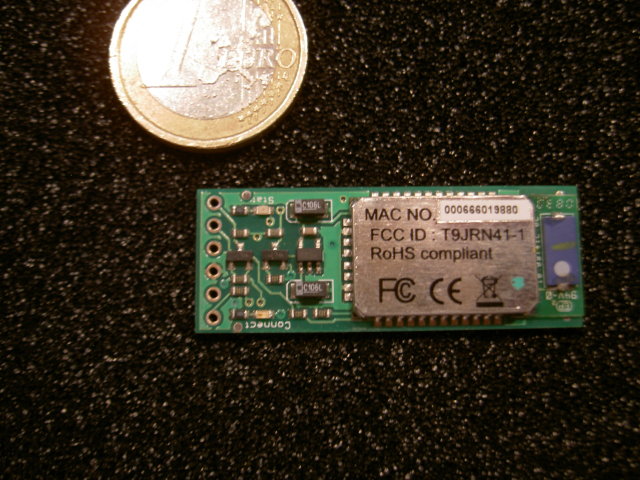
    This is what a typical BT module will look like:


    Some BT modules have more pins than others for adding extra LEDs or buttons, but you really only need the four basic pins:
    1) Data Transmit (Tx)
    2) Data Recieve (Rx)
    3) Ground (-)
    4) Power (+5v)

    Your module should come with a spec sheet that tells you what each pin is.

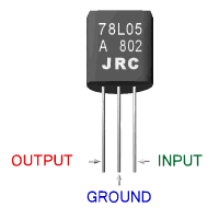
    This is the 78L05 Voltage Regulator:


    Your ECM has a 12v output. This chip will drop that down to a max 5v, so we can power the BT chip right through the ECM without needing batteries.

    You can find these for about $0.25 a piece, but you may have to dump $2 for a pack of 10 and hand the rest out as Halloween candy. Check eBay.

    Here is a pic of the connector plug:


    This is the part that plugs into your ECM connector. go ahead and solder your 4 pieces of wire to the pins and assemble the connector. I usually use Black(-), Red(+), Yellow(Rx), and Brown(Tx), but you can use whatever.

    If you're looking at the back of the plug (with wires sticking out towards you) and the clip on top, here is a pinout:

    Top Left: +12v (no wire in the picture)
    Top Right: Tx to ECM
    Lower Left: Rx from ECM
    Lower Right: -12v

    Go ahead and solder the four wires into the connector pins, and assemble the connector.

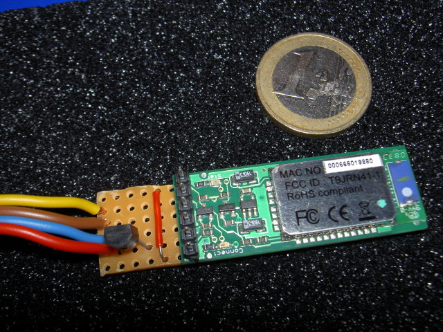
    Now we're ready to assemble the BT circuit.


    The [+12v] wire from the ECM will go into the Voltage Regulator (VR) input. If you're looking at the flat side of the VR with the pins pointed down, it should be on the far right.

    The [-] wire from the ECM will go to the center pin on the VR, then also connect to the (-) on the BT module.

    The [Tx] wire will connect to the Tx pin on the BT module

    The [Rx] wire will connect to the Rx pin on the BT module.

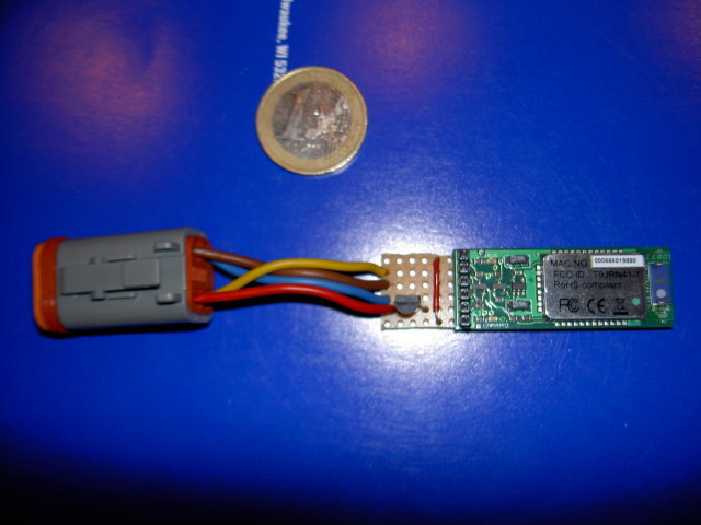
    The completed unit should look something like this:


    You're pretty much done at this point. You can make it watertight, either by sealing it in a box, or dipping it in some sort of "Plasti-Dip" coating (you can find it in the paint section at Lowes or Home Depot).

    Now just follow the software setup instructions that should have come with your BT module.

    Here's a general guideline for setup:

    1) Turn your Buell ignition to "On", make sure the kill switch is set to "Run" (BT will only have power when the ECM is activated)
    2) Activate the BT console on your laptop
    3) Search for new devices. It should find your new BT ECMSpy cable.
    4) Set up the BT Serial Connection, take note of the COM port it is assigned to.
    5) Start ECMSpy, choose the BT Serial COM port.
    6) Connect!

    Like I said, super-quick write up. If I left anything out, please chime in and let me know. I'll try to answer any questions as best I can.

    Again, thanks to Gunter at ECMSpy for cleaning up the design and taking most of these pictures.

    -Tim

  2. #2
    Senior Member
    Join Date
    Apr 2009
    Posts
    248
    I'll try and build a USB one using one of these:

    http://www.sparkfun.com/commerce/pro...oducts_id=9434

    it has the same four pins, only thing that is interesting is that it gets forced to 12Mhz as the USB standard

    do you happen to know at what rate the bluetooth modules you guys have used run at? obviously the actual wireless is still 2.4 Ghz, and as long as the ECM sends bits at under 12Mhz you would be solid assuming the USB device itself can understand varying speeds from the ECM

    hmmm I'll see what I can dig up

    if we can pop one together at $15 a piece I'm sure plenty of people would jump for them

    thanks a ton for the write-up!

  3. #3
    Senior Member
    Join Date
    May 2009
    Posts
    381
    I would really be sweet to do some data logging via wireless, a couple times i parked the bike and spaced out that i was plugged into laptop still


    I would definitely been interested in making or buying one of these

  4. #4
    Senior Member
    Join Date
    Dec 2009
    Posts
    1,307
    awesome job urban. And thorivola...yes I'm sure that people that use ecmspy regularly would jump on a low cost bluetooth unit. I was thinking about using the DIY above and building my own but I think I'll wait to see what you come up with.

  5. #5
    Senior Member
    Join Date
    Dec 2008
    Posts
    223
    Thor-

    Yup, thats exactly what I had in mind. The issue I think we may run into is if the dongle relies on PC software to initiate the SPP layer stack.

    In the modules we used before, the SPP was completely self contained and ready to Tx/Rx as soon as power was applied.

    I was going to take a regular female USB extension, replace the male end with the Buell plug, splice the 5v VR onto the power feed, then plug the dongle into the female end.

    Would be a dirt-cheap solution, and just plug another USB dongle into the end if one gets fried.

    -Tim

  6. #6
    Senior Member
    Join Date
    Apr 2009
    Posts
    248
    I assume because it uses a standard driver that they all behave in the same way. If the stack wasn't set-up internally it would have to have some kind of chip-specific driver.

    Some of the various dongles have driver discs with them, but none of these do and that mini bluetooth adapter doesn't either

    it'll be just shy of two weeks before I can actually try one of these out

  7. #7
    I have not been able to find a cheeper bluetooth serial module than the $50 that is in the picture. Where is everybody else getting theirs. Also if it is not going to be removed from the bike do you really need to buy the plug. It seems like you could just solder wires to some pins and insert them into the plug on the bike.

  8. #8
    Senior Member
    Join Date
    May 2009
    Posts
    503
    Ok you guys are speaking Mongolian to me. If some one can get some pretty cheap made, let me know and I will look into getting one if the price is right.

  9. #9
    Senior Member
    Join Date
    Jan 2007
    Posts
    186
    From experience the 5v Sparkfun died after a couple days. there techs were very sure I put the wrong voltage to the chip. which I didnt, I even staged it to 3.3 volts and tested. same result on that 3.3/5 volt chip it lost connection and would never reconnect. sent all 4 chips back to be tested the input on each chip was burned out. reason they said was heat and duty cycle. as well as it was not meant to be used as an automotive device. Tim and I discussed this a few times on chips I was trying attempting to get lower cost chips each time I ended back at the A7 chips. they make industrial chips and chips for the medical equipment and ect. zigbee is anothe chip that held out. But it was big bucks.

    I did try a few different places and made different setups from the original design we ended up with at first. every chip died except the ones from A7 engineering.


    on the usb dongle I tested a few ways but seemed to find every time it needs a driver to function. If one can find a company that produces a usb unit that does not need a driver and can link automatically or sync with buttons you would be in.

    I'll get out my parts and do some pics of the setup Tim and I did we did he did I did that was did/done. heck I'll make one from scratch for the pics. will post soon.

    Off to put the camera On charge.


    edit A7 links are dead And i cant find them now.I will keep searching.

    will dig into my big book of parts for good numbers on industrial updated chips.
    I do have a new source for the buell plug and part numbers. military spec.
    mike

  10. #10
    Senior Member
    Join Date
    Jan 2007
    Posts
    186
    Ok did some digging. looks like the spark fun chips are different than before. These are reading much better on there pdf files. voltage is setup as no level shift and stable to where they are needed. This unlike the first units I had on the rx and tx. those had lower voltage that was lower.

    I would say the spark fun as I just looked it up is an OK source now. I stand corrected depending on new and improved units.

    The spark fun also offers the socks at 90 deg cheap and a case for a good price.this will clean up assembly. make sure you get a connection button that external and the additional led to see its working. with shipping your going to be aprox 100.00 by the time you get finished.

    when looking up these chips on lower cost. make sure they are not level shifting and the rx/tx line are also 5 volt stable. plus the unit needs to run firmware free stand alone as a cable replacement rs232.


Page 1 of 7 123 ... LastLast

Similar Threads

  1. Wireless ECM cable?
    By Carl0s in forum Buell Firebolt XB12, XB9
    Replies: 0
    Last Post: 04-28-2013, 01:10 AM
  2. How to Build a BETTER Wireless ECMSpy Cable!
    By Urban_Assault in forum Do-It-Yourself Buell Mods
    Replies: 4
    Last Post: 02-24-2012, 07:46 PM
  3. buell wireless ecmspy cable
    By dvers03 in forum Buell Parts for Sale
    Replies: 6
    Last Post: 05-20-2010, 07:03 PM
  4. Wireless ECMSpy
    By Urban_Assault in forum Buell Lightning XB12S, XB12Ss, CityX, XB12Scg
    Replies: 11
    Last Post: 01-30-2009, 08:23 PM
  5. Wireless ECMSpy - $149.00 !!!!!!
    By Urban_Assault in forum General Motorcycle Chat
    Replies: 7
    Last Post: 01-26-2009, 03:05 PM

Posting Permissions

  • You may not post new threads
  • You may not post replies
  • You may not post attachments
  • You may not edit your posts
  •